To reduce the length of the wiring harnesses in vehicles and save on weight, the Bosch company developed the so-called CAN bus for networking control units in 1987. CAN is the abbreviation for "Controller Area Network" and is often used in combination with "bus" (Binary Unit System) to describe a system for the transmission of data between different devices on a shared transmission path.
CANopen is a communication protocol based on CAN that is mainly used in automation equipment for networking complex or time-critical machines and systems. Since 1995, it has been under the care of the CAN in Automation (CiA) organization and it is laid out in the European standard EN 50325-4. CANopen standardizes not only the lower communication level, like RS485 does, but also the command structure for various device types.
Advantages
- Very robust technology, ideally suited for line topologies with very short stubs and twisted-pair cables
- Up to 127 nodes/devices in one network, multi-axis support
- High-speed transmission with data rates of up to 1 Mbit/s
- Standardized protocol, applies to various device types
Nanotec offers motor controllers as well as brushless DC motors and stepper motors with integrated controller and CANopen interface.
Nanotec controllers are based on the CiA402 standard for electrical drives and compatible with products from other manufacturers.
Nanotec is a member of CAN in Automation (CiA), the international users’ and manufacturers’ group for the CAN network.
CANopen services
The CANopen stack offers the services listed in the following table; more detailed descriptions can be found in the respective chapters.
| Default CAN-ID | Service | Description in |
|---|---|---|
| 000 | Network Management (NMT) | Section Network Management (NMT) |
| 080h | Synchronization Object | Section Synchronization object (SYNC) |
| 080h+Node-lD | Emergency | Section Emergency Object (EMCY) |
| 180h+Node-lD | TX Process Data Objects (PDO) | Section Process Data Object (PDO) |
| 200h+Node-lD | RX Process Data Objects (PDO) | Section Process Data Object (PDO) |
| 280h+Node-lD | TX Process Data Objects (PDO) | Section Process Data Object (PDO) |
| 300h+Node-lD | RX Process Data Objects (PDO) | Section Process Data Object (PDO) |
| 380h+Node-lD | TX Process Data Objects (PDO) | Section Process Data Object (PDO) |
| 400h+Node-lD | RX Process Data Objects (PDO) | Section Process Data Object (PDO) |
| 480h+Node-lD | TX Process Data Objects (PDO) | Section Process Data Object (PDO) |
| 500h+Node-lD | RX Process Data Objects (PDO) | Section Process Data Object (PDO) |
| 580h+Node-lD | TX Service Data Objects (SDO) | Section Service Data Object (SDO) |
| 600h+Node-lD | RX Service Data Objects (SDO) | Section Service Data Object (SDO) |
| 700h+Node-lD | BOOT-UP Protocol | Section Boot-Up Protocol |
| 700h+Node-lD | Nodeguarding and Heartbeat | Section Heartbeat and nodeguarding |
Network Management (NMT)
Network Management is oriented towards CANopen devices and follows a master-slave structure. NMT requires a CANopen device in the network that performs the role of the CANopen master. All other devices have the role of the NMT slave. Each NMT slave can be addressed via its individual node-lD in the range from [1-127]. NMT services can be used to initiate, start, monitor, reset or stop CANopen devices.
In doing so, the controller follows the state diagram shown in the following figure. The "lnitialization" state is only reached after switching on or by sending a "Reset Communication" or "Reset Node" NMT command. The "Pre-Operational" state is automatically activated after initialization.
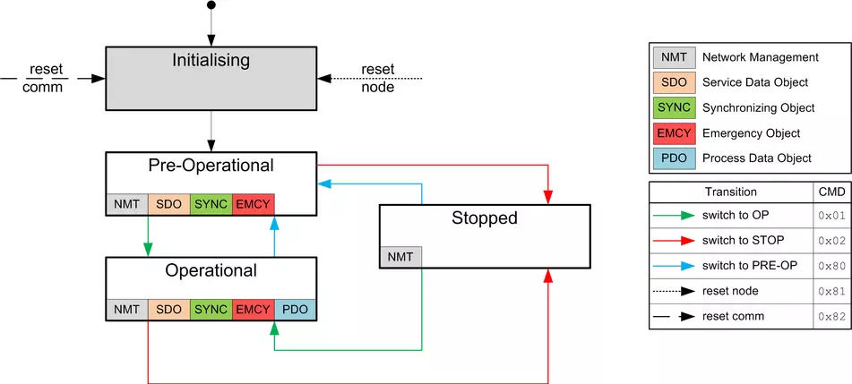
Shown in the following table is an overview of the activity of the services in the respective states. Note that the Stopped state stops communication completely and only permits controller of the NMT state machine.
| Service | lnitializing | Pre-Operational | Operational | Stopped |
|---|---|---|---|---|
| PDO | Active | |||
| SDO | Active | Active | ||
| SYNC | Active | Active | ||
| EMCY | Active | Active | ||
| BOOT-UP | Active | |||
| NMT | Active | Active | Active |
The "Network Management" message has CAN-ID 0. A message is always two bytes lang and has the following structure:
Here, the <CMD> corresponds to one of the following bytes (see also the legend in the figure of the <link knowledge-base-article canopen-motors-controllers _top>NMT state diagram):
| <CMD> | Meaning |
|---|---|
| 01h | Switch to the "Operational" state |
| 02h | Switch to the "Stop" state |
| 80h | Switch to the "Pre-Operational" state |
| 81h | Reset Node |
| 82h | Reset Communication |
The value for <Node-ID> can be 00h; in this case, the NMT command applies for all devices on the CAN bus (broadcast). lf a number not equal to zero is used, only the device with the corresponding node-lD is addressed.
Synchronization object (SYNC)
The Synchronization object is used to simultaneously validate the time of PDO data for all devices on the bus. The sync message is structured as follows:
For SYNC operation, transmission mode (Transmission Type) 0 is normally used for the RX-PDOs (data are valid with the next SYNC); for TX-PDOs, a transmission mode between 1 and 240 is selected. (Details: see <link knowledge-base-article canopen-motors-controllers _top>Process Data Object (PDO)).
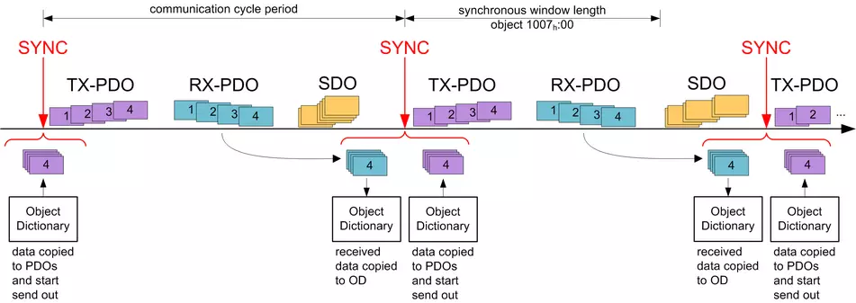
After receiving a SYNC message, there is a time window ("synchronous window") within which PDO messages can be sent and received. lf the time of the window has elapsed, all devices must stop sending PDOs.
A typical CAN-SYNC operation is divided into four phases (see also the following figure):
- The SYNC message is received. The previously received RX-PDO data are thereby copied to the object dictionary (if present). At that time, the data are also sampled and copied to the TX-PDOs and the sending of these messages initiated.
- The TX-PDOs are then sent by all slaves on the bus.
- Afterwards, the PDOs are sent by the CANopen master. After the "synchronous window length" time has elapsed, no further PDOs are permitted.
- SDO messages can be exchanged at the latest when the "synchronous window" is closed again.
Emergency Object (EMCY)
A message of type "Emergency" is sent whenever an error occurs in the controller that was not caused by an SDO access. This service is unconfirmed and is sent with CAN-ID 80h+Node-lD.
The emergency message is structured as follows:
A total of three error codes are transferred here: the "Emergency Error Code" ( <EMCY Error Code>), the content of the "Error Register'' object (1001 h, <E-REG>) and a manufacturer-specific code (Manufacturer Specific Error)
Error handling
A module for error handling processes all errors that occur internally. Each error is classified into an error class.
Each error that occurs is handled as follows:
- The bit that belongs to the error in the "Error Register" object (1001h) is set.
- Three pieces of information are then written together in the "Pre-defined Error Field" object (1003h:01 ):
- The Emergency Error Code
- The Error Register
- The manufacturer-specific error code - lf no further errors are pending, the following message is sent:
80 + Node-ID 1 00 00 00 00 00 00 00 00
Service Data Object (SDO)
A "Service Data Object" permits read or write access of the object dictionary.
In the following, the owner of the object dictionary is referred to as the "server''; the CAN node - which wants to request or write the data - is referred to as the "client". An "upload" refers to the reading of a value of an object from the object dictionary; a "download" refers to the writing of a value in the object dictionary. In addition, the following abbreviations are used in the diagrams:
- <IDX>: Index of the object that is to be read or written in the object dictionary; the LSB of the index is in byte 1 here. Example: The statusword of the controller has index 6041h; byte 1 is then written with 41h and byte 2 with 60h.
- <SUBIDX>: Subindex of the object in the object dictionary from 00h to FFh.
Because CAN messages of type SDO contain a large amount of metadata, SDO messages should only be used to configure the controller. Should it be necessary to exchange data cyclically during running operation, it makes more sense to make use of CANopen messages of type PDO (see <link knowledge-base-article canopen-motors-controllers _top>Process Data Object).
The SDO transfers are divided into three types of access:
- "expedited transfer" for transferring objects with up to four bytes.
- "normal transfer" for transferring any number of bytes, whereby each CAN message is confirmed individually.
- "block transfer" is also for any number of bytes; here, a given block of CAN tickets is confirmed at once.
An SDO message is sent to CAN-ID 600h + node-lD, the answer comes from CAN-ID 580h + node-lD.
Expedited Transfer
This method is used to write (download) or read (upload) values in objects of type (UN)SIGNEDS, INTEGER16 oder INTEGER32 in the object dictionary. This service is confirmed, i.e., each access is answered with data, with a confirmation or with an error message.
SDO Download
An expedited SDO message for writing data in the object dictionary of the server is structured as follows:
Here, the <CMD> byte is dependent on the length of the data that are to be written. <CMD> can be one of the following values:
- 1 byte data length: 2Fh
- 2 byte data length: 2Bh
- 3 byte data length: 27h
- 4 byte data length: 23h
The <Data> field is written with the data that are to be written; the LSB of the data is entered in byte 4.
The answer from the server is either a confirmation of the write operation or an error message (structure of the messages: see following figure). In the latter case, the reason for the error is also sent with the data (see list of the SDO error messages in section <link knowledge-base-article canopen-motors-controllers _top>SDO error messages).
Example
Set object 607Ah:00h (target position, SIGNED32) to value 3E8h (=1000d) of a controller with node-ID 3:
603 | 23 7A 60 00 E8 03 00 00
- Byte 1 (23h): SDO expedited download, 4 bytes of data (SIGNED32)
- Bytes 2 and 3 (7Ah 60h): index of object is 607Ah
- Byte 4 (00h): subindex of object is 00h
- Bytes 5 to 8 (E8h 03h 00h 00h): value of object: 000003E8h
lf successful, the controller responds with this message:
583 | 60 7A 60 00 00 00 00 00
SDO upload
A CAN message for reading an object from the object dictionary has the following structure:
The server responds with one of the following messages:
The length of the data is encrypted in the <CMD> of the answer:
- 1 byte data length: 4Fh
- 2 byte data length: 4Bh
- 3 byte data length: 47h
- 4 byte data length: 43h
The LSB of the data is again in byte 4 here.
In case of an error, the reason for the error is also specified in the data (see list of SDO error messages in <link knowledge-base-article canopen-motors-controllers _top>SDO error messages).
Example
To read the "statusword" object (6041h:00) from the object dictionary, it suffices to send the following message (always 8 bytes):
603 | 40 41 60 00 00 00 00 00
The controller generally responds with the following message:
583 | 4B 41 60 00 40 02 00 00
Where
- Byte 1 (4Bh): SDO expedited upload, 2 bytes of data (UNSIGNED16)
- Bytes 2 and 3 (41h 60h): index of object is 6041h
- Byte 4 (00h): subindex of object is 00h
- Bytes 5 to 6 (40h 02h): value of object: 0240h
- Bytes 7 to 8 (00h 2h): empty. An SDO message always consists of 8 bytes.
SDO error messages
In case of an error, an error number specifying the reason for the error is also sent in the data area.
| Error Code | Description |
|---|---|
| 05030000h | toggle bit not changed: Valid only with "normal transfer" or "block transfer". The bit, which is to alternate after each transfer, did not change its state. |
| 05040000h | command specifier unknown: Byte 0 of the data block contains a command that is not allowed. |
| 06010000h | unsupported access: lf "complete access" was requested via CAN over EtherCAT (CoE) (is not supported.) |
| 06010002h | read only entry: An attempt was made to write to a constant or read-only object. |
| 06020000h | object not existing: An attempt was made to access a non-existing object (index incorrect). |
| 06040041h | object cannot be pdo mapped: An attempt was made to map an object in the PDO for which that is not permissible. |
| 06040042h | mapped pdo exceed pdo: lf the desired object were to be attached to the PDO mapping, the 8 bytes of the PDO mapping would be exceeded. |
| 06070012h | parameter length too long: An attempt was made to write to an object with too much data; for example, with <CMD>=23h (4 bytes) to an object of type Unsigned8, <CMD>=2Fh would be correct. |
| 06070013h | parameter length too short: At attempt was made to write to an object with too little data; for example, with <CMD>=2Fh (1 byte) to an object of type Unsigned32, <CMD>=23h would be correct. |
| 06090011h | subindex not existing: An attempt was made to access an invalid subindex of an object; the index, on the other hand, would exist. |
| 06090031h | value too great: Same objects are subject to restrictions in the size of the value; in this case, an attempt was made to write an excessively large value to the object. For example, the "Pre-defined error field: Number of errors" object for 1003h:00 may only be set to the value "0"; all other numerical values result in this error. |
| 06090032h | value too small: Same objects are subject to restrictions in the size of the value. In this case, an attempt was made to write a value that is too small to the object. |
| 08000000h | general error: General error that does not fit in any other category. |
| 08000022h | data cannot be read or stored in this state: The parameters of the PD Os may only be changed in the "Stopped" or "Pre-Operational" state. Write access of objects 1400h to 1407h, 1600h to 1607h, 1800h to 1807h and 1A00h to 1A07h is not permissible in the "Operational" state. |
Process Data Object (PDO)
A message that only contains process data is referred to as a "Process Data Object" (PDO). The PDO
is intended for data that need to be exchanged cyclically. The idea behind a PDO message is to remove all additional information (index, subindex and data length) from a CAN message and to only fill the CAN message with data. The source and target information for the PDO are stored separately in the so-called PDO mapping.
PDOs can only be used if the NMT state machine is in the "Operational" state (see <link knowledge-base-article canopen-motors-controllers _top>Network Management (NMT)); the PDOs must be configured in the "Pre-Operational" NMT state.
The controller supports a total of eight independent PDO mappings; each corresponding PDO message can have a maximum of eight bytes (=64 bit) of user data. lt is thereby possible to, for example, transfer two UNSIGNED32 values or one UNSIGNED32 and one UNSIGNED0B; the message does not need to use all eight data bytes. The PDOs differ yet again in the configuration in the send and receive configuration. The receive configuration describes the processing for PDO messages that are sent, and the send configuration describes the PDO messages that are to be sent.
Rx configuration
To configure an RX-PDO, three object categories in the object dictionary must be taken into account:
- The objects that describe the functionality of the mapping.
- The objects that describe the content of the mapping.
- The objects that are to receive the received data.
Configuration of the functionality (communication parameter)
The configuration of the first mapping is stored in the subindices of object 1400h. The second mapping is configured in 1401h and so on. In the following, we refer to 140Nh. Here, the configuration affects the COB-1D of the PDO message and the transfer type.
Objects 140Nh have only three subindices:
- Subindex 0 (max. subindex): Total number of subindices
- Subindex 1 (COB-1D): The COB-1D is stored here. For PDO mappings 1-4 (1600h-1603h), the CAN-1D is fixed depending on the node-1D and only the valid bit (bit 31) can be set in the COB-1D. From 1604h-1607h, the CAN-ID can be set independently (with the restriction that it not be used by other services, see table ) as can the valid bit. The change of a COB-ID does not take effect until afterthe controller or communication is restarted (see <link knowledge-base-article canopen-motors-controllers _top>Network Management (NMT)).
| Mapping | COB-ID |
|---|---|
| 1600h | 200h + Node-ID |
| 1601h | 300h + Node-ID |
| 1602h | 400h + Node-ID |
| 1603h | 500h + Node-ID |
| 1604h | XXXh + Node-ID |
| 1605h | XXXh + Node-ID |
| 1606h | XXXh + Node-ID |
| 1607h | XXXh + Node-ID |
- Subindex 2 (transmission type): A number is stored in this subindex that defines the time at which the received data become valid. The number and the corresponding meaning can be found in the following table.
| 140Nh:02h | Meaning |
|---|---|
| 00h-F0h | Synchronous: The data are buffered and not until the next SYNC message is received do they become valid and are they taken over into the object dictionary. |
| F1h-FDh | Reserved |
| FEh,FFh | Asynchronous: The data become valid when the PDO message is received and are taken over into the object dictionary. |
Content of a mapping
The configuration of the content of a mapping is structured as follows (see also the following figure as an example):
- All subindices of a configuration object belang together. Thus, 1600h with all subindices describes the first mapping, 1601h the second RX-PDO mapping, etc.
- Subindex 00h specifies how many objects are in a mapping. lt simultaneously specifies how many of the subindices are valid. lf object 1600h:00h is set to "0", RX mapping is thereby completely switched off. In the example shown in the following figure, two objects are thus mapped; object 1600h:03h and 1600h:04h is, therefore, not active (shown in gray).
- Each subindex from 1600h:01h to 1600h:0Fh describes one target of the mapping sequentially and without gaps. The index, subindex and bit length are thereby encoded. Example from the following figure: The first two bytes of the message are to be written in object 6040h:00h. In hexadecimal notation, the content of 1600h:01h then consists of
<Index><Subindex><Bit length>
or 60400010. The second mapping (1600h:02h) contains the entry 607A0020. Thus, it maps the following four bytes (=20h ßit) in object 607Ah:00h
TX configuration
To configure an TX-PDO, three object categories in the object dictionary must be taken into account:
- The objects that describe the functionality of the mapping.
- The objects that describe the content of the mapping.
- The objects that are to receive the data that are to be sent.
Also note that the time at which the data are copied to the TX-PDO message and the time of sending do not need to be the same (dependent on mode).
Configuration of the functionality (communication parameter)
The configuration of the functionality of the first mapping is stored in the subindices of object 1800h. The second mapping is configured in 1801h and so on. In the following, we refer to 180Nh. Here, the configuration affects the COB-ID of the PDO message and the transfer type.
Objects 180Nh have the following subindices:
- Subindex 0 (max. subindex): Total number of subindices
- Subindex 1 (COB-ID): The COB-ID is stored here. For PDO mappings 1--4 (1A00h-1A03h), the CAN-ID is fixed depending on the node-ID and only the valid bit (bit 31) can be set in the COB-ID. From 1A04h-1A07h, the CAN-ID can be set independently (with the restriction that it not be used by other services, see table ) as can the valid bit. A COB-ID change does not take effect until after the controller or communication is restarted (see Network Management (NMT)).
| Mapping | COB-ID |
|---|---|
| 1A00h | 180h + Node-ID |
| 1A01h | 280h + Node-ID |
| 1A02h | 380h + Node-ID |
| 1A03h | 480h + Node-ID |
| 1A04h | XXXh + Node-ID |
| 1A05h | XXXh + Node-ID |
| 1A06h | XXXh + Node-ID |
| 1A07h | XXXh + Node-ID |
- Subindex 2 (transmission type): A number is stored in this subindex that defines the time at which the data are to be copied into the PDO message and when this is to be sent. The number and the corresponding meaning can be found in the following table. Below, we refer to an Event that can trigger the copying and/or sending of the data. This Event consists of three events, which can be considered independently of one another:
- The NMT state machine is switched to "operational".
- The current data have changed with respect to the last PDO message.
- The Event Timer has expired (see 180Nh:5).
lf the Event Timer is used, it is handled independently of the changes; the Event Timer is not restarted until the current event timer expires, not because of another Event.
| 180Nh:02h | Meaning |
|---|---|
| 0 | Synchronous (acyclic): The data are copied to the TX-PDO upon arrival of the SYNC but are not sent until the Event. |
| 01h-F0h | Synchronous (cyclic): The data are copied upon arrival of the nth SNCY message and are sent immediately thereafter (n corresponds to the number 1 to 240, transmission type "1" sends the new data on each SYNC). |
| F1h-FBh | Reserved |
| FCh | RTR-Only (synchronous): The data are copied upon arrival of each SYNC message but are sent only upon request with an RTR message. |
| FDh | RTR-Only (event-driven): The data are copied to the TX-PDO message upon receipt of an RTR message and sent immediately thereafter. |
| FEh,FFh | The data are copied upon arrival of the Event and sent immediately. |
- Subindex 3 (inhibit time): This subindex contains a time lock (see following figure). This can be used to set a time that must elapse after the sending of a PDO before the PDO is sent another time. This time only applies for asynchronous PDOs. This is intended to prevent PDOs from being sent continuously if the mapped object constantly changes.
- Subindex 4 (compatibility entry): This subindex has no function and exists only for compatibility reasons.
- Subindex 5 (event timer): This time can be used to trigger an Event which handles the copying of the data and the sending of the PDO.
- Subindex 6 (sync start value): Here, the start value of the Sync Counter is entered beginning with which the s/ave is to initially respond to the sync and send the PDO. Not globally activated until a value greater than 1 is set in 1019h Synchronous Counter Overflow Value.

Content of mapping
The configuration of the content of a mapping is structured as follows (see the following figure as an example):
- All subindices of a configuration object belang together. Thus, 1A00h with all subindices describes the first mapping, 1A01h the second TX-PDO mapping, etc.
- Subindex 00 specifies how many objects are in a mapping. lt simultaneously specifies how many of the subindices are valid. lf object 1A00h:00h is set to "0", TX mapping is thereby completely switched off. In the following example, two objects are thereby mapped in entries 1A00h:01h - 1A00h:02h - The objects in entries 1A00h:03h - 1A00h:04h are, thus, not mapped (shown in gray).
- Each subindex from 1A00h:01h to 1A00h:0Fh respectively describes sequentially and without gaps (dummy objects can be used for gaps) one source of the mapping. The index, subindex and bit length are thereby encoded. Example from the following figure: The first two bytes of the message are to be read from object 6041h:00h. In hexadecimal notation, the content of 1A00h:01h then consists of <Index><Subindex><Bit Length>, or 60410010. The second mapping (1A00h:02h) contains the entry 60640020. Thus, it maps the following four bytes (corresponds to 32 bits) from object 6064h:00h in the TX-PDO message.
Boot-Up Protocol
lf the CAN slave reaches the "Pre-Operational" NMT state (see following figure), the following message is sent to signal operational readiness.
This service is unconfirmed; there is no response.
Heartbeat and nodeguarding
With the "heartbeat" and "nodeguarding" services (often also referred to as "lifeguarding"), switched-off or hung devices on the CAN bus can be detected. For this purpose, the NMT master cyclically requests a message with the current NMT state of the slave (nodeguarding). The alternative is that each slave sends a message unprompted and cyclically (heartbeat). A combination of nodeguarding and heartbeat is not permissible. Furthermore, it is recommended that heartbeat be given preference over nodeguarding, as nodeguarding results in a higher load on the CAN bus.
Nodeguarding
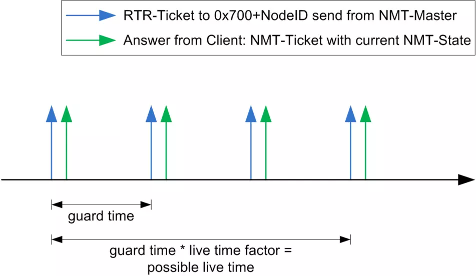
This service is based on the fact that the NMT master sends an RTR message with CAN-ID 700h + nodeID to the respective slave. The slave must then send a message as response; this message is structured as follows. Bit 7 alternates here on each transfer, thereby allowing one to determine if a message was lost. Entered in bits 6 to 0 is the current NMT status of the slave.
With nodeguarding, there exist three time intervals (see also the following figure):
- guard time: The time between two RTR messages. This can be different for each CAN node and is stored in the slave in object 100Ch:00 (unit: milliseconds)
- live time factor: A multiplier for the guard time; this is stored in the CAN slave in object 1 00Dh:00 and can be different for each slave on the CAN bus.
- possible live time: The time produced by multiplying guard time and live time factor.
The following conditions are checked during nodeguarding:
- The NMT master must send the RTR request within the "possible live time".
- The slave must send the response to the RTR request within the "possible live time".
- The slave must respond with its NMT state. In addition, the "toggle bit" must be set correctly.
Heartbeat
lf heartbeat is activated, the slave sends its NMT state to the CAN bus unprompted and cyclically. This service is activated by setting the Producer Heartbeat Time time in object 1017h:00h to a value other than zero. The message sent by the slave has the form shown below:
The slave must send the heartbeat message within the Heartbeat Consumer Time. This time is known only to the master and is not stored in the controller.
Errors that occur du ring this monitoring are reset if either the function is deactivated or the Heartbeat is again sent within the correct time.

