Pin assignment
Overview

| Connection | Function |
|---|---|
| X1 | EtherCAT IN and OUT |
| X2 | Encoder and Hall sensor connection |
| X3 | Digital/analog inputs and outputs |
| X4 | Brake connection |
| X5 | Motor connection |
| X6 | Voltage supply |
| X7 | Micro USB connection |
| L1 | Power LED |
X1 − EtherCAT IN and OUT
Type: RJ45 socket
Pin 1 is marked with an asterisk "*". Both connectors are configured identically according to the following table.

| Pin | Function | Note |
|---|---|---|
| 1 | TD+ | |
| 2 | TD- | |
| 3 | RD+ | |
| 4 | n.c. | |
| 5 | n.c. | |
| 6 | RD- | |
| 7 | n.c. | |
| 8 | n.c. |
X2 – encoder/Hall sensor
- Type: JST S12B-PADSS-1
- Mating connector (not included in scope of delivery):
- Housing: JST PADP-12V-1-S (or equivalent)
- Contacts: JST SPH-001T-P0.5L (or equivalent)
- Suitable Nanotec cables (not included in the scope of delivery):
- ZK-PADP-12-500-S
- ZK-M12-8-2M-2-PADP
- ZK-M12-12-2M-2-PADP
- ZK-NTO3-10-500-PADP / ZK-NTO3-10-1000-PADP
- ZK-NOE-10-500-S-PADP
- ZK-WEDL-500-S-PADP
Pin 1 and pin 2 are marked in the figure.

| Pin | Function | Note |
|---|---|---|
| 1 | GND | |
| 2 | Vcc | 5 V DC, output and supply voltage for encoder / Hall sensor; max. 200 mA |
| 3 | A | 5 V signal, max. 1 MHz |
| 4 | B | 5 V signal, max. 1 MHz |
| 5 | A\ | 5 V signal, max. 1 MHz |
| 6 | B\ | 5 V signal, max. 1 MHz |
| 7 | I | 5 V signal, max. 1 MHz |
| 8 | I\ | 5 V signal, max. 1 MHz |
| 9 | Hall 1 | 5 V signal |
| 10 | Hall 2 | 5 V signal |
| 11 | Hall 3 | 5 V signal |
| 12 | Shielding | Shielding |
The following switching thresholds apply for the encoder inputs:
| Type | Switching thresholds | |
|---|---|---|
| On | Off | |
| Single | > 3.8 V | < 0.26 V |
| Difference | > 3.8 V | < 0.26 V |
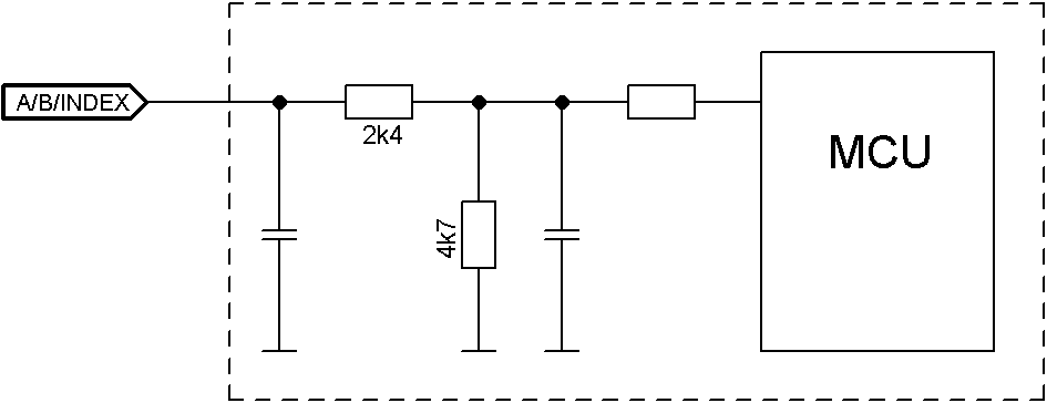
The internal wiring of the encoder inputs is shown in the following.
X3 – inputs and outputs
- Type: Phoenix Contact MC 0.5/12-G-2.5
- Mating connector (included in scope of delivery): Phoenix Contact FK-MCP 0.5/12-ST-2.5 (or equivalent)
- Nanotec article number: ZCPHOFK-MC0,5-12
Pin 1 is marked with an asterisk "*".

| Pin | Function | Note |
|---|---|---|
| 1 | +10 V DC | Output voltage, max. 200 mA |
| 2 | Digital input 1 | 5 V / 24 V signal, switchable by means of software with object 3240h, max. 1 MHz; clock input in clock-direction mode |
| 3 | Digital input 2 | 5 V / 24 V signal, switchable by means of software with object 3240h, max. 1 MHz; direction input in clock-direction mode |
| 4 | Digital input 3 | 5 V / 24 V signal, switchable by means of software with object 3240h |
| 5 | Digital input 4 | 5 V / 24 V signal, switchable by means of software with object 3240h |
| 6 | Digital input 5 | 5 V / 24 V signal, switchable by means of software with object 3240h |
| 7 | Analog input 1 | 10 bit, 0-10 V or 0-20 mA, switchable by means of software with object 3221h |
| 8 | Analog input 2 | 10 bit, 0-10 V, not switchable by means of software |
| 9 | Digital output 1 | Open drain, maximum 24 V / 100 mA |
| 10 | Digital output 2 | Open drain, maximum 24 V / 100 mA |
| 11 | Digital output 3 | Open drain, maximum 24 V / 100 mA |
| 12 | GND |
| Max. Voltage | Switching thresholds | |
|---|---|---|
| On | Off | |
| 5 V | > 3.8 V | < 0.26 V |
| 24 V | > 14.42 V | < 4.16 V |
The following applies for the analog inputs:
| Configuration of analog input | Input resistance (maximum value) |
|---|---|
| Voltage input | approx. 147 kOhm |
| Current input (analog input 1 only) | at 1 mA: approx. 350 ohm |
| Current input (analog input 1 only) | at 20 mA: approx. 283 ohm |
| Connection data | min | max |
|---|---|---|
| Conductor cross section, rigid, min. | 0.14 mm2 | 0.5 mm2 |
| Conductor cross section, flexible, min. | 0.14 mm2 | 0.5 mm2 |
| Conductor cross section, flexible, min. Wire-end sleeve without plastic sleeve, min. | 0.25 mm2 | 0.5 mm2 |
| Conductor cross section, min. AWG | 26 | 20 |
| Min. AWG acc. to UL/CUL | 28 | 20 |
X4 – brake connection
- Type: Phoenix Contact MC 0.5/2-G-2.5
- Mating connector (included in scope of delivery): Phoenix Contact FK-MCP 0.5/2-ST-2.5 (or equivalent)
- Nanotec article number: ZCPHOFK-MC0,5-2
Pin 1 is marked with an asterisk "*".

| Pin | Function | Note |
|---|---|---|
| 1 | Brake + | Internally connected to +UB |
| 2 | Brake - | PWM-controlled open-drain output, max. 1.5 A |
| Connection data | min | max |
|---|---|---|
| Conductor cross section, rigid, min. | 0.14 mm2 | 0.5 mm2 |
| Conductor cross section, flexible, min. | 0.14 mm2 | 0.5 mm2 |
| Conductor cross section, flexible, min. Wire-end sleeve without plastic sleeve, min. | 0.25 mm2 | 0.5 mm2 |
| Conductor cross section, min. AWG | 26 | 20 |
| Min. AWG acc. to UL/CUL | 28 | 20 |
X5 – motor connection
- Type: Würth Elektronik 691313510004
- Mating connector (included in scope of delivery): Würth Elektronik 691353500004 (or equivalent)
- Nanotec article number: ZCPHOFKC-2,5HC-4
Pin 1 is marked with an asterisk "*".

| Pin | Function (Stepper) | Function (BLDC) |
|---|---|---|
| 1 | A | U |
| 2 | A\ | V |
| 3 | B | W |
| 4 | B\ | Not used |
| Connection data | min | max |
|---|---|---|
| Conductor cross section, rigid, min. | 0.2 mm2 | 1.5 mm2 |
| Conductor cross section, flexible, min. | 0.2 mm2 | 1.5 mm2 |
| Conductor cross section, flexible, min. Wire-end sleeve without plastic sleeve, min. | 0.25 mm2 | 1.5 mm2 |
| Conductor cross section, flexible, min. Wire-end sleeve min. Plastic sleeve min. | 0.25 mm2 | 0.75 mm2 |
| Conductor cross section, min. AWG | 24 | 16 |
| Min. AWG acc. to UL/CUL | 24 | 16 |
X6 – voltage supply
- Type: Würth Elektronik 691313510002
- Mating connector (included in scope of delivery): Würth Elektronik 691353500002 (or equivalent)
- Nanotec article number: ZCPHOFKC-2,5HC-2
Voltage source
The operating or supply voltage supplies a battery, a transformer with rectification and filtering, or a switching power supply.
Connections
Pin 1 is marked with an asterisk "*".

| Pin | Function | Note |
|---|---|---|
| 1 | +UB | 12 V - 48 V DC, ±5% |
| 2 | GND |
| Connection data | min | max |
|---|---|---|
| Conductor cross section, rigid, min. | 0.2 mm2 | 1.5 mm2 |
| Conductor cross section, flexible, min. | 0.2 mm2 | 1.5 mm2 |
| Conductor cross section, flexible, min. Wire-end sleeve without plastic sleeve, min. | 0.25 mm2 | 1.5 mm2 |
| Conductor cross section, flexible, min. Wire-end sleeve min. Plastic sleeve min. | 0.25 mm2 | 0.75 mm2 |
| Conductor cross section, min. AWG | 24 | 16 |
| Min. AWG acc. to UL/CUL | 24 | 16 |
Permissible operating voltage
The maximum operating voltage is 50.4 V DC. If the input voltage of the controller exceeds the threshold value set in 2034h, the motor is switched off and an error triggered. Above the response threshold set in 4021h:02h, the integrated ballast circuit is activated (wirewound resistor CR257-05T15R from VITROHM with 5 W continuous output).
The minimum operating voltage is 11.4 V DC. If the input voltage of the controller falls below 10 V, the motor is switched off and an error triggered.
A charging capacitor of at least 4700 µF / 50 V (approx. 1000 µF per ampere rated current) must be connected in parallel to the supply voltage to avoid exceeding the permissible operating voltage (e.g., during braking).
X7 − Micro USB
A cable of type "micro USB" is needed for this USB connection.
