Pin assignment
Overview

| Connection | Function |
|---|---|
| X1 | Modbus RTU IN and OUT |
| X2 | Encoder and Hall sensor connection |
| X3 | Digital/analog inputs and outputs |
| X4 | Brake connection |
| X5 | Motor connection |
| X6 | Voltage supply |
| X7 | Micro USB connection |
| S1 | 150 ohm termination resistor (switch set to ON) |
| S2 | Hex coding switch for slave address and baud rate, 16s place (e.g., F0h) |
| S3 | Hex coding switch for slave address and baud rate, 1s place (e.g., 0Fh) |
| L1 | Power LED |
X1 – Modbus RTU (RS-485) IN and OUT
Type: RJ45 socket
Pin 1 is marked with an asterisk "*". Both connectors are configured identically according to the following table.

| Pin | Function | Note |
|---|---|---|
| 1 | n.c. | |
| 2 | n.c. | |
| 3 | n.c. | |
| 4 | RS-485+ | |
| 5 | RS-485- | |
| 6 | n.c. | |
| 7 | n.c. | Pin 7 of the two connectors internally connected to one another |
| 8 | COMMON | Pin 8 of the two connectors connected to one another |
RS-485 line polarization
- A pull-up resistor to a 5V voltage on the RS-485+ (D1) cable
- A pull-down resistor to earth (GND) on the RS-485- (D0) cable
In this case, a line polarization must be attached at a location for the entire serial bus. In general, this location should be on the master device or its connection. All other devices then no longer need to implement line polarization.

X2 – encoder/Hall sensor
- Type: JST S12B-PADSS-1
- Mating connector (not included in scope of delivery):
- Housing: JST PADP-12V-1-S (or equivalent)
- Contacts: JST SPH-001T-P0.5L (or equivalent)
- Suitable Nanotec cables (not included in the scope of delivery):
- ZK-PADP-12-500-S
- ZK-M12-8-2M-2-PADP
- ZK-M12-12-2M-2-PADP
- ZK-NTO3-10-500-PADP / ZK-NTO3-10-1000-PADP
- ZK-NOE-10-500-S-PADP
- ZK-WEDL-500-S-PADP
Pin 1 and pin 2 are marked in the figure.

| Pin | Function | Note |
|---|---|---|
| 1 | GND | |
| 2 | Vcc | 5 V DC, output and supply voltage for encoder / Hall sensor; max. 200 mA |
| 3 | A | 5 V signal, max. 1 MHz |
| 4 | B | 5 V signal, max. 1 MHz |
| 5 | A\ | 5 V signal, max. 1 MHz |
| 6 | B\ | 5 V signal, max. 1 MHz |
| 7 | I | 5 V signal, max. 1 MHz |
| 8 | I\ | 5 V signal, max. 1 MHz |
| 9 | Hall 1 | 5 V signal |
| 10 | Hall 2 | 5 V signal |
| 11 | Hall 3 | 5 V signal |
| 12 | Shielding | Shielding |
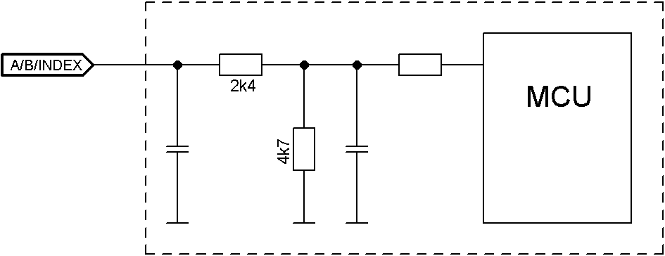
The following switching thresholds apply for the encoder inputs:
| Type | Switching thresholds | |
|---|---|---|
| On | Off | |
| Single | > 3.8 V | < 0.26 V |
| Difference | > 3.8 V | < 0.26 V |
The internal wiring of the encoder inputs is shown in the following.
X3 – inputs and outputs
- Type: Phoenix Contact MC 0.5/12-G-2.5
- Mating connector (included in scope of delivery): Phoenix Contact FK-MCP 0.5/12-ST-2.5 (or equivalent)
- Nanotec article number: ZCPHOFK-MC0,5-12
Pin 1 is marked with an asterisk "*".

| Pin | Function | Note |
|---|---|---|
| 1 | +10 V DC | Output voltage, max. 200 mA |
| 2 | Digital input 1 | 5 V / 24 V signal, switchable by means of software with object 3240h, max. 1 MHz; clock input in clock-direction mode |
| 3 | Digital input 2 | 5 V / 24 V signal, switchable by means of software with object 3240h, max. 1 MHz; direction input in clock-direction mode |
| 4 | Digital input 3 | 5 V / 24 V signal, switchable by means of software with object 3240h |
| 5 | Digital input 4 | 5 V / 24 V signal, switchable by means of software with object 3240h |
| 6 | Digital input 5 | 5 V / 24 V signal, switchable by means of software with object 3240h |
| 7 | Analog input 1 | 10 bit, 0-10 V or 0-20 mA, switchable by means of software with object 3221h |
| 8 | Analog input 2 | 10 bit, 0-10 V, not switchable by means of software |
| 9 | Digital output 1 | Open drain, maximum 24 V / 100 mA |
| 10 | Digital output 2 | Open drain, maximum 24 V / 100 mA |
| 11 | Digital output 3 | Open drain, maximum 24 V / 100 mA |
| 12 | GND |
| Max. Voltage | Switching thresholds | |
|---|---|---|
| On | Off | |
| 5 V | > 3.8 V | < 0.26 V |
| 24 V | > 14.42 V | < 4.16 V |
The following applies for the analog inputs:
| Configuration of analog input | Input resistance (maximum value) |
|---|---|
| Voltage input | approx. 147 kOhm |
| Current input (analog input 1 only) | at 1 mA: approx. 350 ohm |
| Current input (analog input 1 only) | at 20 mA: approx. 283 ohm |
| Connection data | min | max |
|---|---|---|
| Conductor cross section, rigid, min. | 0.14 mm2 | 0.5 mm2 |
| Conductor cross section, flexible, min. | 0.14 mm2 | 0.5 mm2 |
| Conductor cross section, flexible, min. Wire-end sleeve without plastic sleeve, min. | 0.25 mm2 | 0.5 mm2 |
| Conductor cross section, min. AWG | 26 | 20 |
| Min. AWG acc. to UL/CUL | 28 | 20 |
X4 – brake connection
- Type: Phoenix Contact MC 0.5/2-G-2.5
- Mating connector (included in scope of delivery): Phoenix Contact FK-MCP 0.5/2-ST-2.5 (or equivalent)
- Nanotec article number: ZCPHOFK-MC0,5-2
Pin 1 is marked with an asterisk "*".

| Pin | Function | Note |
|---|---|---|
| 1 | Brake + | Internally connected to +UB |
| 2 | Brake - | PWM-controlled open-drain output, max. 1.5 A |
| Connection data | min | max |
|---|---|---|
| Conductor cross section, rigid, min. | 0.14 mm2 | 0.5 mm2 |
| Conductor cross section, flexible, min. | 0.14 mm2 | 0.5 mm2 |
| Conductor cross section, flexible, min. Wire-end sleeve without plastic sleeve, min. | 0.25 mm2 | 0.5 mm2 |
| Conductor cross section, min. AWG | 26 | 20 |
| Min. AWG acc. to UL/CUL | 28 | 20 |
X5 – motor connection
- Type: Würth Elektronik 691313510004
- Mating connector (included in scope of delivery): Würth Elektronik 691353500004 (or equivalent)
- Nanotec article number: ZCPHOFKC-2,5HC-4
Pin 1 is marked with an asterisk "*".

| Pin | Function (Stepper) | Function (BLDC) |
|---|---|---|
| 1 | A | U |
| 2 | A\ | V |
| 3 | B | W |
| 4 | B\ | Not used |
| Connection data | min | max |
|---|---|---|
| Conductor cross section, rigid, min. | 0.2 mm2 | 1.5 mm2 |
| Conductor cross section, flexible, min. | 0.2 mm2 | 1.5 mm2 |
| Conductor cross section, flexible, min. Wire-end sleeve without plastic sleeve, min. | 0.25 mm2 | 1.5 mm2 |
| Conductor cross section, flexible, min. Wire-end sleeve min. Plastic sleeve min. | 0.25 mm2 | 0.75 mm2 |
| Conductor cross section, min. AWG | 24 | 16 |
| Min. AWG acc. to UL/CUL | 24 | 16 |
X6 – voltage supply
- Type: Würth Elektronik 691313510002
- Mating connector (included in scope of delivery): Würth Elektronik 691353500002 (or equivalent)
- Nanotec article number: ZCPHOFKC-2,5HC-2
Voltage source
The operating or supply voltage supplies a battery, a transformer with rectification and filtering, or a switching power supply.
Connections
Pin 1 is marked with an asterisk "*".

| Pin | Function | Note |
|---|---|---|
| 1 | +UB | 12 V - 48 V DC, ±5% |
| 2 | GND |
| Connection data | min | max |
|---|---|---|
| Conductor cross section, rigid, min. | 0.2 mm2 | 1.5 mm2 |
| Conductor cross section, flexible, min. | 0.2 mm2 | 1.5 mm2 |
| Conductor cross section, flexible, min. Wire-end sleeve without plastic sleeve, min. | 0.25 mm2 | 1.5 mm2 |
| Conductor cross section, flexible, min. Wire-end sleeve min. Plastic sleeve min. | 0.25 mm2 | 0.75 mm2 |
| Conductor cross section, min. AWG | 24 | 16 |
| Min. AWG acc. to UL/CUL | 24 | 16 |
Permissible operating voltage
The maximum operating voltage is 50.4 V DC. If the input voltage of the controller exceeds the threshold value set in 2034h, the motor is switched off and an error triggered. Above the response threshold set in 4021h:02h, the integrated ballast circuit is activated (wirewound resistor CR257-05T15R from VITROHM with 5 W continuous output).
The minimum operating voltage is 11.4 V DC. If the input voltage of the controller falls below 10 V, the motor is switched off and an error triggered.
A charging capacitor of at least 4700 µF / 50 V (approx. 1000 µF per ampere rated current) must be connected in parallel to the supply voltage to avoid exceeding the permissible operating voltage (e.g., during braking).
X7 − Micro USB
A cable of type "micro USB" is needed for this USB connection.

S1 – termination resistor
This DIP switch switches the termination of 150 Ω between RS-485+ and RS-485- (see X1 – Modbus RTU (RS-485) IN and OUT). The "down" switch position switches termination on.

S2 – Modbus slave address and baud rate
For setting the slave address and baud rate. The value of this switch is multiplied by 16 and added to the value of switch S3; this switch thereby sets the 16s place. See chapter Communication settings.

S3 – Modbus slave address and baud rate
For setting the slave address and baud rate. The value of this switch is added to the value of switch S2; this switch thereby sets the 1s place. See chapter Communication settings.

|
Example |
|
| Switch S2 is set to the value 1h, switch S3 to the value Fh; the result is the value 1Fh for setting the address and baud rate. | |