Pin assignment
Overview

| Connection | Function |
|---|---|
| X1 | Voltage supply |
| X2 | Motor connection |
| X3 | Micro USB |
| X4 | RS-232 connection |
| X5 | Digital/analog inputs and outputs |
| X6 | Encoder/Hall sensor |
| X7 | CANopen / RS-485 IN |
| X8 | CANopen / RS-485 OUT |
| S1 | Switch for 120 ohm termination resistor |
| J1 | Jumper: switches between CAN_L or RS-485- |
| J2 | Jumper: switches between CAN_H or RS-485+ |
| L1 | Status LED green |
| L2 | Status LED red |
X1 – voltage supply
Voltage source
The operating or supply voltage supplies a battery, a transformer with rectification and filtering, or a switching power supply.
Connections
Connector type: JST XH
Suitable Nanotec cable: ZK-XHP2-500-S (not included in the scope of delivery)
In the following figure, pin 1 is marked with a "1".

| Pin | Function | Note |
|---|---|---|
| 1 | +UB |
12 V - 24 V ±5% |
| 2 | GND |
Permissible operating voltage
The maximum operating voltage is 25.2 V DC. If the input voltage of the controller exceeds the threshold value set in 2034h, the motor is switched off and an error triggered. Above the response threshold set in 4021h:02h, the integrated ballast circuit is activated (wirewound resistor Z32041412209K6C000 from Vishay with 3 W continuous output).
The minimum operating voltage is 11.4 V DC. If the input voltage of the controller falls below 10 V, the motor is switched off and an error triggered.
A charging capacitor of at least 4700 µF / 50 V (approx. 1000 µF per ampere rated current) must be connected to the supply voltage to avoid exceeding the permissible operating voltage (e.g., during braking).
X2 – motor connection
Connector type: JST XH
Suitable Nanotec cable: ZK-XHP4-300 (not included in the scope of delivery)
In the following figure, pin 1 is marked with a "1".

| Pin | Function (stepper motor) | Function (BLDC) |
|---|---|---|
| 1 | A | U |
| 2 | A\ | V |
| 3 | B | W |
| 4 | B\ | Not used |
X3 − Micro USB

X4 − RS-232 connection
Connector type: JST GH
Suitable Nanotec cable: ZK-GHR3-500-S (not included in the scope of delivery)
In the following figure, pin 1 is marked with a "1".

| Pin | Function | Note |
|---|---|---|
| 1 | RS-232-RX | |
| 2 | RS-232-TX | |
| 3 | GND |
X5 – digital/analog inputs and outputs
Connector type: JST GH
Suitable Nanotec cable: ZK-GHR12-500-S (not included in scope of delivery)
In the following figure, pin 1 is marked with a "1".

| Pin | Function | Note |
|---|---|---|
| 1 | +10 V DC | Output voltage, max. 200 mA |
| 2 | Digital input 1 | 5 V signal, max. 1 MHz |
| 3 | Digital input 2 | 5 V signal, max. 1 MHz |
| 4 | Digital input 3 | 5 V signal, max. 1 MHz ("direction" in clock-direction mode) |
| 5 | Digital input 4 | 5 V signal, max. 1 MHz ("clock" in clock-direction mode) |
| 6 | Digital input 5 | 5 V signal, max. 1 MHz |
| 7 | Analog input 1 | 10 bit, 0-10 V or 0-20 mA, switchable by means of software with object 3221h, default setting: 0-10 V |
| 8 | Analog input 2 | 10 bit, 0-10 V, not switchable by means of software |
| 9 | Digital output 1 | Open drain, max. 24 V/100 mA |
| 10 | Digital output 2 | Open drain, max. 24 V/100 mA |
| 11 | Digital output 3 | Open drain, max. 24 V/100 mA |
| 12 | GND |
|
Switching thresholds (worst-case calculations) |
|
|---|---|
| On | Off |
| > 4.25 V | < 0.75 V |
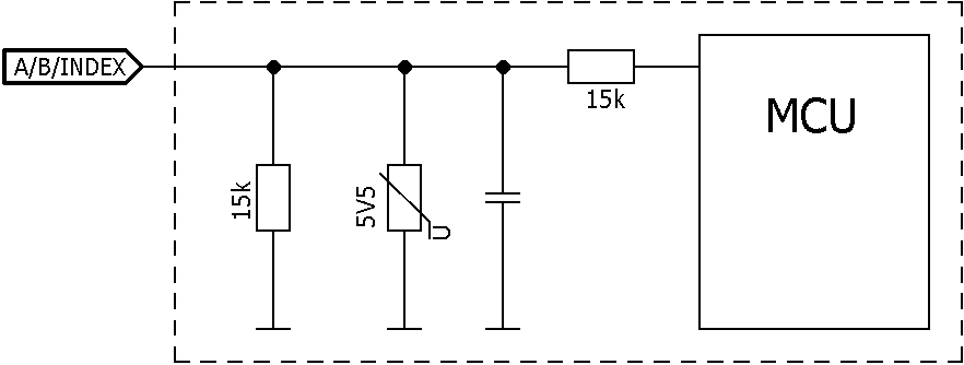
The current consumption is approximately 0.4 mA. The following internal circuit diagram applies for the digital inputs:

X6 – encoder/Hall sensor
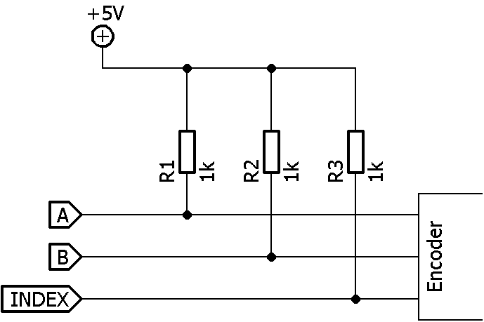
The controller with hardware version W004b does not function with the following encoders without additional wiring (see below):
- WEDS5541
- WEDS5546
- HEDS5540
With these encoders, a PULL-UP resistor must be connected to 5 V on cables A, B and INDEX.
Connector type: JST GH
Suitable Nanotec cables (not included in the scope of delivery):
- ZK-GHR13-500-S-GHR (for Nanotec encoder NME)
- ZK-MCM-12-500-S-JXH (for Nanotec encoder NME)
- ZK-GHR10-500-S-GHR (for Nanotec encoder NOE)
- ZK-TM4-10-500-S-JXH (for Nanotec encoder NTO3)
- ZK-JZH-8-500-S-JXH (for Nanotec encoder WEDL)
In the following figure, pin 1 is marked with a "1".

| Pin | Function | Note |
|---|---|---|
| 1 | +5 V DC | Supply voltage for encoder/Hall sensor, max. 200 mA |
| 2 | A | 5 V signal, max. 1 MHz |
| 3 | B | 5 V signal, max. 1 MHz |
| 4 | Index | 5 V signal |
| 5 | H1 | 5 V signal, max. 1 MHz |
| 6 | H2 | 5 V signal, max. 1 MHz |
| 7 | H3 | 5 V signal, max. 1 MHz |
| 8 | GND |
The following switching thresholds apply for the encoder inputs:
| Switching thresholds | |
|---|---|
| Switching on | Switching off |
| > approx. 2.8 V | < approx. 1.1 V |
The internal wiring of the encoder inputs is shown in the following.
X7 − CANopen/RS-485 IN
Connector type: JST GHR
Suitable Nanotec cable: ZK-PD4-C-CAN-4-500-S (not included in the scope of delivery)
In the following figure, pin 1 is marked with a "1".

| Pin | CANopen function | RS-485 function | Note |
|---|---|---|---|
| 1 | +UB Logic | +UB Logic | 24 V DC input, external logic supply for communication, input voltage, current consumption approx. 36 mA |
| 2 | CAN+ | RS-485+ | The changeover is performed via jumper J2. |
| 3 | CAN- | RS-485- | The changeover is performed via jumper J1. |
| 4 | GND | GND |
Should the main supply fail, the logic supply keeps the electronics, the encoder and the communication interface in operation.
The windings of the motor are not supplied by the logic supply.
RS-485 line polarization
- A pull-up resistor to a 5V voltage on the RS-485+ (D1) cable
- A pull-down resistor to earth (GND) on the RS-485- (D0) cable
In this case, a line polarization must be attached at a location for the entire serial bus. In general, this location should be on the master device or its connection. All other devices then no longer need to implement line polarization.

X8 − CANopen/RS-485 OUT
Connector type: JST GHR
Suitable Nanotec cable: ZK-PD4-C-CAN-4-500-S (not included in the scope of delivery)
In the following figure, pin 1 is marked with a "1".

| Pin | CANopen function | RS-485 function | Note |
|---|---|---|---|
| 1 | +UB Logic | +UB Logic | 24 V DC input, external logic supply for communication, input voltage, current consumption approx. 36 mA |
| 2 | CAN+ | RS-485+ | The changeover is performed via jumper J2. |
| 3 | CAN- | RS-485- | The changeover is performed via jumper J1. |
| 4 | GND | GND |
Should the main supply fail, the logic supply keeps the electronics, the encoder and the communication interface in operation.
The windings of the motor are not supplied by the logic supply.
RS-485 line polarization
- A pull-up resistor to a 5V voltage on the RS-485+ (D1) cable
- A pull-down resistor to earth (GND) on the RS-485- (D0) cable
In this case, a line polarization must be attached at a location for the entire serial bus. In general, this location should be on the master device or its connection. All other devices then no longer need to implement line polarization.
S1 – termination resistor

A termination with 120 ohm between CAN+ and CAN- or RS-485- and RS-485+ can thereby be switched on or off.
Jumper J1/J2
With these jumpers, it is possible to change between CANopen or RS-485.
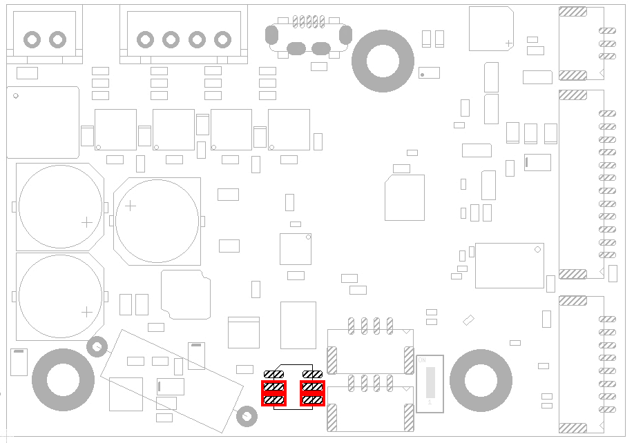
RS-485 setting
To use the RS-485 bus, jumpers J1 and J2 must be plugged in facing the middle of the board (see following figure).
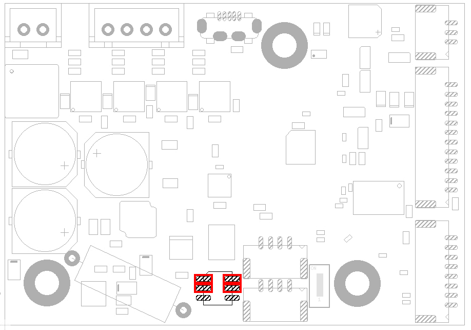
CANopen setting
To use the CANopen bus, jumpers J1 and J2 must be plugged in facing the edge of the board (see following figure).