Pin assignment
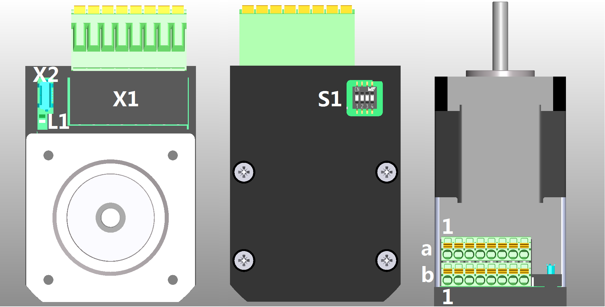
Overview
| Connection | Function |
|---|---|
| X1 | Voltage supply, inputs and outputs |
| X2 | Micro USB |
| S1 | DIP switch |
| L1 | Power LED |
X1 – voltage supply, inputs and outputs
Voltage source
The operating or supply voltage supplies a battery, a transformer with rectification and filtering, or a switching power supply.
Connections
- Type: Phoenix Contact MCDN 1.5/ 8-G1-3.5 P26THR
- Mating connector (included in scope of delivery): 2x Phönix Contact FMC 1.5/ 8-ST-3.5 (or equivalent)
- Nanotec article number: ZCPHOF-MC1,5-8
| Pin | Function | Note |
|---|---|---|
| a1 | GND | |
| a2 | +Ub |
|
| a3 | Digital input 1 | 24 V signal, max. 1 MHz |
| a4 | Digital input 2 | 24 V signal, max. 1 MHz |
| a5 | Digital input 3 | 24 V signal, max. 1 MHz |
| a6 | Analog input | 10 bit, 0-10 V or 0-20 mA, switchable by means of software with 3221h |
| a7 | Digital output 1 | Open drain, max. 24 V/100 mA |
| a8 | Digital output 2 | Open drain, max. 24 V/100 mA |
| b1 | GND | |
| b2 | +10 V DC | Constant output voltage, max. 150 mA |
| b3 | -Release (-input 4) | The default setting for this input combination is "single-ended"; this means that the "-Release" input is deactivated, only "+Release" against GND is active. 5 V / 24 V signal, switchable by means of software with object 3240h, max. 1 MHz |
| b4 | +Release (+input 4) | |
| b5 | –Direction (–input 5) | The default setting for this input combination is "single-ended"; this means that the "-Direction" input is deactivated, only "+Direction" against GND is active. 5 V / 24 V signal, switchable by means of software with object 3240h, max. 1 MHz |
| b6 | Direction (+input 5) | |
| b7 | –Clock (–input 6) | The default setting for this input combination is "single-ended"; this means that the "-Clock" input is deactivated, only "+Clock" against GND is active. 5 V / 24 V signal, switchable by means of software with object 3240h, max. 1 MHz |
| b8 | Clock (+input 6) |
| Max. Voltage |
Switching thresholds (worst-case calculations) |
|
|---|---|---|
| On | Off | |
| 24 V | > 15.29 V | < 0.97 V |
| Max. Voltage |
Switching thresholds (worst-case calculations) |
|
|---|---|---|
| On | Off | |
| 5 V | > 4.94 V | < 0.48 V |
| 24 V | > 20.24 V | < 2.94 V |
If you set 3240h:07h to the value "1", three differential inputs are available on pins b3 to b8. Where:
| Switching on | Switching off |
|---|---|
| Voltage at input pin+ against GND > switch-on threshold | Voltage at input pin- against GND > switch-on threshold |
| Connection data | min | max |
|---|---|---|
| Conductor cross section, rigid, min. | 0.2 mm2 | 1.5 mm2 |
| Conductor cross section, flexible, min. | 0.2 mm2 | 1.5 mm2 |
| Conductor cross section, flexible, min. Wire-end sleeve without plastic sleeve, min. | 0.25 mm2 | 1.5 mm2 |
| Conductor cross section, flexible, min. Wire-end sleeve min. Plastic sleeve min. | 0.25 mm2 | 0.75 mm2 |
| Conductor cross section, min. AWG | 24 | 16 |
| Min. AWG acc. to UL/CUL | 24 | 16 |
Permissible operating voltage
Depending on the motor type, the maximum operating voltage is:
- PD2-C4118L1804: 50.5 V DC.
- PD2-CB42C048040: 50.5 V DC.
- PD2-CB42M024040: 29 V DC.
If the input voltage of the controller exceeds the threshold value set in 2034h, the motor is switched off and an error triggered. Above the response threshold set in 4021h:02h, the integrated ballast circuit is activated (wirewound resistor Z32041412209K6C000 from Vishay with 3 W continuous output).
The minimum operating voltage is 11.4 V DC. If the input voltage of the controller falls below 10 V, the motor is switched off and an error triggered.
A charging capacitor of at least 4700 µF / 50 V (approx. 1000 µF per ampere rated current) must be connected in parallel to the supply voltage to avoid exceeding the permissible operating voltage (e. g., during braking).
X2 − Micro USB
A cable of type "micro USB" is needed for this USB connection.