External ballast circuit
During braking, electrical energy is fed back into the DC-link through self-induction of the motor. If not using a power supply with regenerative-feedback capability, the brake power can cause the DC-link voltage to increase which, if no additional measures are taken, is limited only by the internal consumption and capacitances in the DC-link.
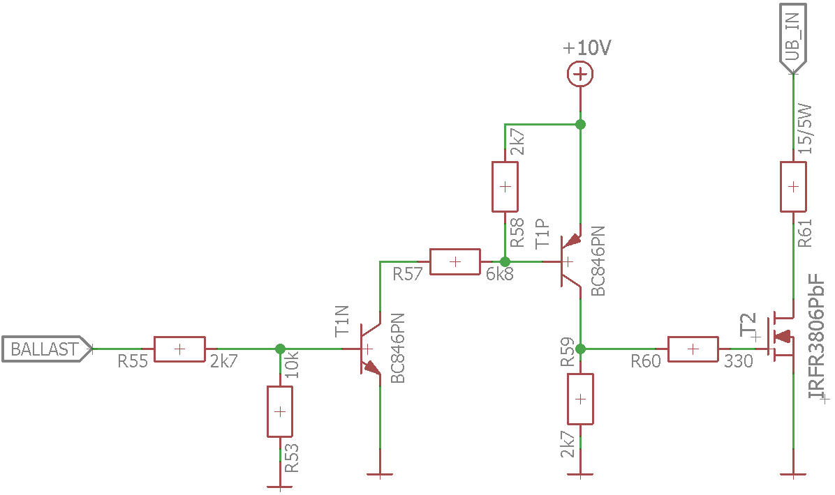
To prevent damage to the controller through overvoltage, it may – depending on the level of the braking power – be necessary to dissipate excess energy in the form of heat. For this purpose, the controller provides an output at pin (pin B27) for controlling an external ballast circuit that consists of a driver, a MOSFET as switch, and a sufficiently dimensioned ballast resistor (see Example of a ballast circuit).
Control of the ballast resistor
A ballast controller and monitor that has two functions is implemented in the firmware of the controller:
- Limitation of the DC-link voltage through activation of the ballast resistor or shutdown of the output stage
- Protection of the ballast resistor against thermal overload
The parameters to be configured are described in the following chapters.
Activating the ballast
To activate the ballast, set bit 0 in 4021h:01h to "1". If you would like to invert the polarity of the pin for controlling the external ballast circuit (B27, on delivery: active high), set bit 1 in 4021h:01h to "1".
Enter the response threshold in millivolts as well as the hysteresis when switching on/off in 4021h:02h and 4021h:03h, respectively.
If, in spite of the activation, the ballast is not able to limit the increase in the DC-link voltage, an error is generated and the driver output stage switched off when the overvoltage threshold (2034h) is exceeded.
Ballast monitoring
The firmware constantly monitors the ballast resistor by adding up the energy it converts – taking into account the thermal energy that the resistor discharges to its surroundings through convection.
If the energy exceeds the permissible limit value, the ballast resistor is blocked from switching on and a warning generated with error code 7113h (see 1003h). After the resistor has cooled sufficiently, the block is automatically canceled.
To configure the monitoring, you must ascertain or determine the following resistor parameters from the data sheet of the ballast resistor and enter them in the corresponding subindex of 4021h:
- Nominal Resistance RBallast, [mOhm]
- Rated value of the ballast resistor
- Cooling Power PStat_TA_Max, [mW]
- The amount of heat that the resistor can/may constantly discharge to its surroundings. You can calculate these as follows:
- Short Term Energy Limit EST_25°C, [mWs]
- Amount of energy that can be supplied to the resistor within a short load surge (<1 second) without overloading it.
- Long Term Energy Limit ELT_TA_Max, [mWs]
- Amount of energy that can be supplied to the resistor within the Long Term Reference Time (see below, typically between 1 and 5 seconds) without overloading it.
- Long Term Reference Time tLT_Ref, [ms]
- The reference time for the Long Term Energy Limit (typically between 1 and 5 seconds)
If the parameters are not valid or realistic, an error is generated with error code 7110 h (see 1003h).
Example of a ballast circuit
The following section from the circuit diagram of the NP5 Discovery Board (see Hardware installation), can serve as a reference for the development of your own ballast circuit.

The used ballast resistor is a CR257-05T15R from VITROHM. The circuit is controlled via pin BALLAST (B27).
The following parameters, which you enter in the corresponding subindex of 4021h, are based on the data sheet values and the installation position on the Discovery Board:
| Subindex | Parameter | Value |
|---|---|---|
| 04h | Nominal Resistance | 15000 |
| 05h | Long Term Energy Limit | 162714 |
| 06h | Long Term Reference Time | 1000 |
| 07h | Short Term Energy Limit | 29200 |
| 08h | Cooling Power | 2258 |
