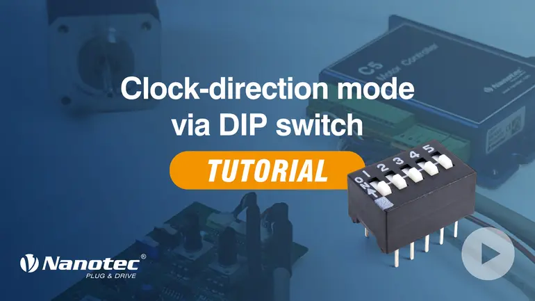
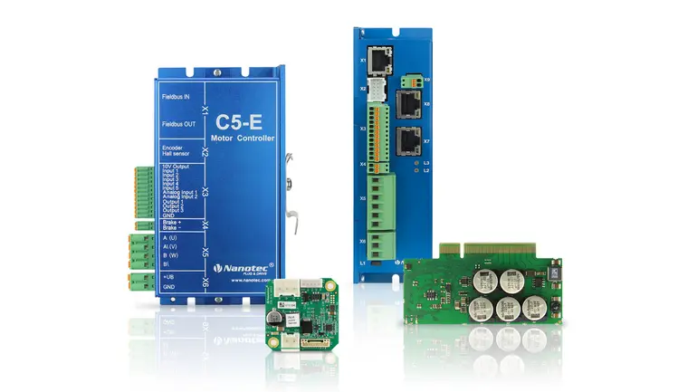
This tutorial shows you how to activate the clock-direction mode on a Nanotec motor controller using the DIP switches mounted on the housing. The setup is done entirely via the hardware…
Più dettagli
Categoria Motor controllers/drives
How to parametrize motor controllers/drives with Nanotec Software
In this video, learn how to quickly and efficiently configure the clock-direction mode using NanoJ software. We'll walk you through the entire process, from setup and parameterization to…
Più dettagli
Firmware update via Ethernet – Troubleshooting
In this video you will learn how to troubleshoot when updating a Nanotec controller via Ethernet. Selecting the right network card and entering the MAC address of the controller will help…
Più dettagli
Firmware update via USB – Troubleshooting
In this video you will learn how to troubleshoot when updating a Nanotec controller via USB. Performing the update in a specific order is a solution if no connection to the bootloader is…
Più dettagli
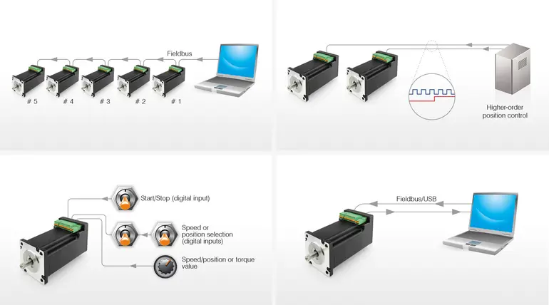
Control methods
The Nanotec controllers and motors with integrated controller can be controlled by means of four different methods. DIP switches, configuration files, or software enable the user to select…
Più dettagli
Webinar: Using motor controllers more efficiently
In this webinar, we introduce the features of motor controllers and brushless DC motors with integrated controller from Nanotec. Learn more about the various control methods, the…
Più dettagli
Auto Setup Tutorial – Plug & Drive Studio
How do you commission the motor controllers from Nanotec with the help of the Plug & Drive Studio? The tutorial shows how to practically perform the auto setup step-by-step using…
Più dettagli
Connecting Nanotec controllers / drives with Ethernet
This application note shows you how to connect a Nanotec controller/drive with Ethernet using a DHCP tool.
Più dettagli
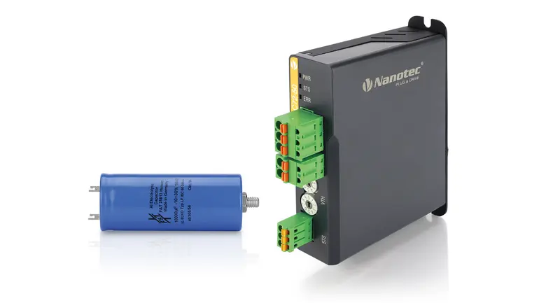
Back-EMF protection with charge capacitor and brake chopper
Smooth out unwanted voltage spikes and protect your controller.
Più dettagli
Configuration files for clock-direction and analog mode
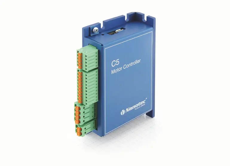
Our C5 controller is preprogrammed for clock-direction and analog speed mode. Here you find the applicable and documented configuration files to edit all settings for these modes…
Più dettagli
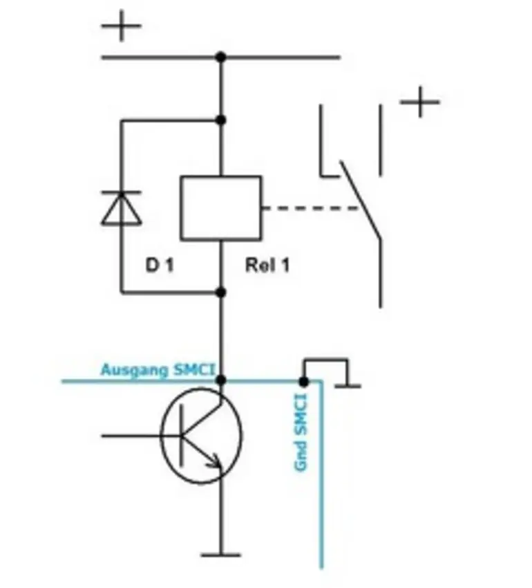
Switching of a load or PLC via the outputs of the motor controller/Plug & Drive motor
The motor controllers and motors with integrated controllers have open collector outputs. To switch a load or PLC, you require a relay according to this circuit diagram. The flyback diode…
Più dettagli
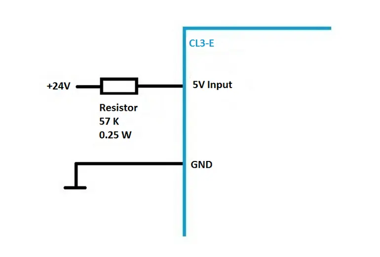
Applying 24V to 5V only digital inputs
The CL3-E controller/drive has 5 V inputs. If a 24 V control signal is to be applied, it will require a 57 kOhm (0.25 W) resistor be connected in series to each input in use.
Più dettagli
The firmware update failed – no more communication
If communication is no longer possible with the motor controller or the motor after a failed firmware update, the firmware can be uploaded manually.
Più dettagli
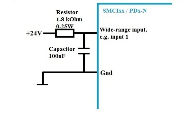
Interference-suppression circuit for overcoupling of 24V control signals
Depending on the cable type, routing and length, an overcoupling onto the neighboring control line may occur with 24 V control signals. In motor controllers/drives with wide range inputs…
Più dettagli
Applying 24V to 5V only digital input for SMCI Series
The controllers SMCI12, SCMI36 and SCMP33 have 5 V inputs. If a 24 V control signal is to be applied, it will require a 39 kOhm (0.25 W) resistor be…
Più dettagli
Motor Controller Basics
Principles of motor controllers: motor model, open loop, closed loop, control loops, modes of operation, firmware, CANopen protocols.
Più dettagli


