NanoSPI
The Serial Peripheral Interface (SPI) is a bus system for a synchronous, serial data bus (Synchronous Serial Port) with which digital circuits can be connected to one another according to the master-slave principle.
Described in this chapter is the protocol developed by Nanotec by means of which you can perform, e.g., CANopen-SDO accesses via SPI. The protocol is a combination of EtherCAT and CANopen and is, thus, a single master protocol.
Bus topology
The SPI bus uses the SCK (source clock), MOSI (master out, slave in), MISO (master in, slave out) and CS (chip select) cables. As no differential signals are used, the GND connection is necessary. The following graphic shows the topology in the simple case of a single slave.

Depending on the expansion stage, multiple slaves can be controlled by one master, see chapter SPI sub-master.
SPI settings
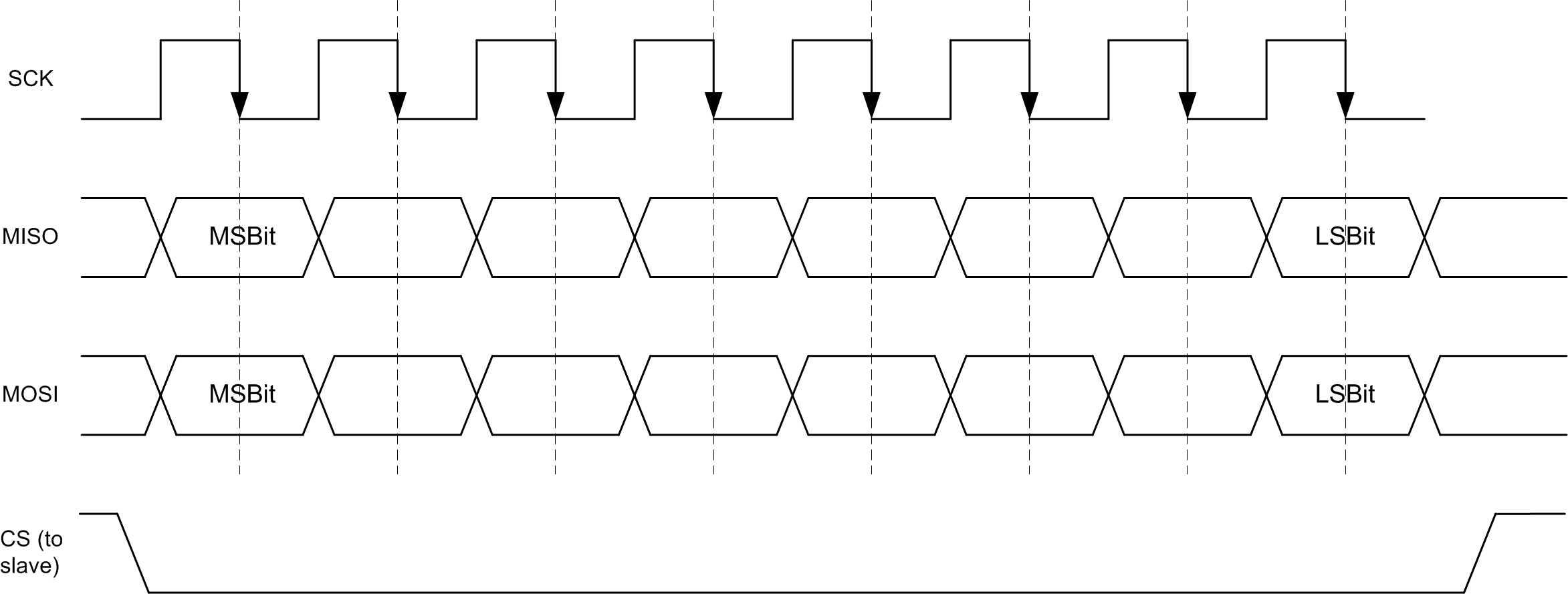
The SPI parameters are to be set as follows (see also the following figure):
- The idle level of the clock signal is low.
- A bit value (MISO and MOSI) is made available on the rising edge of the clock signal.
- The sampling instant is the falling edge of the clock signal.
- The data are sent and received with the Most Significant Bit first.
- The CS signal is low active.
-
As long as the SPI slave has not synchronized with the millisecond cycle of the SPI master, the SPI master may only transfer a message every two milliseconds.
If the SPI is in sync with the millisecond cycle of the SPI master, the SPI master may transfer a message every millisecond.
The SPI slave can be controlled with a maximum frequency of 20 MHz.
The following figure shows the SPI signal curve:
Bus initialization
The slaves do not send valid content until a correct message has been received once from the master. Bus initialization is concluded with the first correctly received message.
General information on the protocol
The expressions listed below are used in the following:
- Message means that data are sent to an individual subscriber.
- Transfer: multiple logically related messages constitute a transfer.
- Mailbox is a data range within a message which, as a container, contains the data of a certain protocol (e.g., SDO protocol). The available protocols are defined; successive messages do not always need to contain the same protocol in the mailbox.
- Map is a data range in the message that transfers selected data from the object dictionary or writes selected data to the object dictionary. If active, this map is transferred with each message. This is very well suited for monitoring important objects from the object dictionary.
Data are selected before activating the map by means of the protocol from the mailbox and can only be changed again under certain conditions.
- Mapping means the assignment of the data within a map.
SPI message
One or no mailboxes can be embedded in an SPI message. The possible mailboxes are described in the following.
Data exchange mailbox
To obtain a response to a mailbox, the SPI master must transfer two messages. The following figure shows the storage sequence of the master and slave for sending and for receiving. During transfer of the very first message to the bus, the content of some of these buffers is not defined.
For the response to request 1, two messages must be sent. The second message can then contain a new request.

Message frequency and synchronization
The messages can be exchanged with the following frequency:
- Asynchronous operation: no more than one message every two milliseconds
- Synchronous operation: one message per millisecond
Synchronization with the messages of the master occurs in the Operational state of the slave. This process can initially take up to 100 milliseconds. Once synchronization is active, the maps of the messages are evaluated. The Operational state of the slave is not displayed until it has synchronized. Until then, the slave remains in the Init state and the master is only permitted to transfer a message every two milliseconds.
If the slave has not received any messages from the master for a period of one second, it is again asynchronous and switches back to the Init state.
If the messages from the master are not transferred on increments of precisely one millisecond (excessive jitter), the slave cannot synchronize or reverts to the Init state after no fewer than 64 messages and is again asynchronous.
Structure of an SPI message
- INFO byte: Describes the protocol used in the mailbox and specifies the bus status of the sender of the message (for details: see INFO byte).
- Mailbox corresponding to the INFO byte: see CANopen mailbox
- Map: if active, see Map
- CRC byte: see CRC

INFO byte
The INFO byte is structured as follows:

| Bits 7-6 | Meaning |
|---|---|
0b00 |
Init operating state:
|
0b01 |
Operational (sync) operating state:
|
0b10 |
Operational (async) operating state:
|
0b11 |
Error operating state
|
| Bits 1-0 | Meaning (see also CANopen mailbox) |
|---|---|
0b00 |
No mailbox |
0b01 |
CANopen mailbox with SDO protocol (see section CANopen SDO protocol) |
0b10 |
CANopen mailbox with 8 invalid data bytes (details: see section CANopen invalid data) |
0b11 |
NanoSPI mailbox (details: see sectionNanoSPI mailbox) |
CANopen mailbox
CANopen SDO protocol
By means of this mailbox, the SDO protocol of the CANopen standard is used. Because no other services can be addressed, the COB-ID is not sent. The mailbox thus contains 8 bytes of an SDO message.
CANopen invalid data
To obtain the confirmation to a request, two SPI messages must be sent: the first with the request and the second for transporting the response (see also Data exchange mailbox). If no other request is to be sent and only the response is to be retrieved, the mailbox of the second message may be of this type.
The data within the mailbox are not relevant; there is no response to the content of this message.
NanoSPI mailbox
NanoJ programs can be transferred via the NanoSPI mailbox. Up to 1024 bytes of user data can be sent per message in this way. Multiple messages can be grouped into a transfer. A mailbox consists of the following four parts:
| Byte position | Name | Description |
|---|---|---|
| 0 | Indication | For displaying the content of the last message of the transfer, etc. |
| 1 | Counter | For numbering the messages within a transfer. Overflow of the counter is confirmed in the Indication byte with a change of the value of the "Toggle bit". |
| 3-2 | Length | Contains the length of the data stored in the data range (unit: bytes). |
| 4 … 1028 | Data | Contains the data (up to 1024 bytes). |
Indication
The Indication byte provides information on the content and on the transfer. The bits are listed in the following table.
| Bit position | Name | Description |
|---|---|---|
| 1-0 | DataType | Type of data:
|
| 2 | Toggle | Each transfer starts with this bit set to the value "0". Every time the counter byte overflows from "255" to "0", the state of the bit must change. |
| 3 | Last message | Shows the last message of the current transfer. |
| 4 | Reset Comm | Resets the transfer. |
| 7-5 | Reserved | These bits must be 0. |
Counter
The Counter byte numbers the messages. On each new transfer, the counter begins with 0. In the event of an overflow from 255 to 0, the Toggle bit in the Indication byte must change state (see following figure).

Length
Length defines the length of the data range (data) in bytes. The maximum length of the data is 1024 bytes.
Data
Data contains the data; the maximum transferable data quantity is 1024 bytes.
Example
In the following example, a NanoJ program consisting of 3204 bytes is to be transferred. The bytes with the value XX are not relevant to the example.
- Send the first 1024 bytes of a NanoJ program; header: mailbox type NanoSPI, bus status Init:
The first message consists of the following bytes:
03 01 00 00 04 XX XX ... XX XXThe bytes of this message have the following meaning:
- Byte 0 =
0x03(Info byte): the NanoSPI mailbox is used, bus status is Init. - Byte 1 =
0x01(Indication byte):- Data type is NanoJ program.
- Toggle bit is set to "0" since a new transfer is taking place.
- LastFrame bit is set to "0" since further data packets will follow.
- Reset Comm bit is set to "0".
- Byte 2 =
0(Counter): This is the first message of the transfer. - Byte 3 / 4 =
0x0400(Length bytes): Byte 4 =0x04, byte 3 =0x00which, together, mean the data length of 1024 bytes in the mailbox. - Byte 5 to byte 1028 (inclusive): These are the first 1024 bytes of the NanoJ program.
- Byte 1029 =
0xXX(CRC byte)
- Byte 0 =
- Send the second 1024 bytes of a NanoJ program; header: mailbox type NanoSPI, bus status Init:
03 01 01 00 04 XX XX ... XX XXUnlike the first message, only the Counter byte was increased to
1and the data are filled with the next 1024 bytes of the NanoJ program. - Send the third 1024 bytes of a NanoJ program; header: mailbox type NanoSPI, bus status Init:
03 01 02 00 04 XX XX ... XX XXUnlike the second message, only the Counter was increased; in addition, the NanoJ data are the third 1024 bytes of the NanoJ program.
- Send the last 132 bytes of a NanoJ program; header: mailbox type NanoSPI, bus status Init:
03 09 03 84 00 XX XX ... XX XXThe bytes of the above message have the following meaning:
- Byte 0 =
0x03(Info byte): The NanoSPI mailbox is used, bus status is Init. - Byte 1 =
0x09(Indication byte):- Data type is NanoJ program.
- Toggle bit set to "0".
- LastFrame bit set to "1" since this is the last message of the transfer.
- Reset Comm bit is set to "0".
- Byte 2 =
3(Counter): This is the fourth message of the transfer. - Byte 3 / 4 =
0x0084(Length bytes): Byte 4 =0x00, byte 3 =0x84which, together, means the data length of 132 bytes in the mailbox. - Byte 5 to byte 136 (inclusive): These are the last 132 bytes of the NanoJ program.
- Byte 137 =
0xXX(CRC byte)
- Byte 0 =
Map
To be able to exchange important objects in the object dictionary with every message, the map can be used. The map consists only of data for or from the object dictionary. Meta information for the transfered data (i.e., the index, subindex and length information) for the map are defined in advance and are not sent.
The map is updated internally every millisecond; all values are current upon retrieval of the data.
General principle
In general, a distinction is always made between a map for receiving (RX) and one for sending (TX).
- RX refers to the data that are received cyclically by the respective controller from the SPI bus and thereby written in the object dictionary of the device.
- TX refers to the data that are read from the object dictionary of the controller and sent to the master.
The incoming data are copied to the object dictionary as shown in the following figure. The TX map is then assembled and sent in the next message.

The assignment of data to objects (mapping) is stored in special objects.
The assignments for receiving data are to be entered in objects 1600h to 1603h and 3500h.
The assignments for sending data are to be entered in objects 1A00h to 1A03h and 3600h.
Mapping becomes active as soon as the SPI bus is switched from Init to Operational. For changes, the bus must be reset to Init, the changes made and the bus then switched back to Operational.
Creating a map
Four objects in the object dictionary define the objects in which the mapping is defined:
-
Two objects for the RX maps: Object 3402h:01h … 3402h:04h for the NanoSPI Ctrl (SLOT_SPI) interface or object 3400h:01h … 3400h:04h for the NanoSPI Comm (COMM_SPI) interface define the active mappings.
Objects 1600h to 1603h or 3500h contain the mapping.
-
Two objects for the TX maps: Object 3403h:01h … 3403h:04h for the NanoSPI Ctrl (SLOT_SPI) interface or object 3401h:01h … 3401h:04h for the NanoSPI Comm (COMM_SPI) interface define the active mappings.

Example:
The following figure shows a section of the object dictionary. All relevant objects for the RX map of the NanoSPI Ctrl (SLOT_SPI) are thereby recorded.
Object 3402h:00h defines the number of active subentries. In the above example = 1, i.e., only subindex 01h is active.
Object 3402h:01h to 3402h:04 defines where the mapping is stored in the object dictionary. In the example, only subindex 01h is active, thus only object 1600h.
The active object for 1600h:00, in turn, specifies how many of the sub-entries are active. In the example, entries 1600h:01h and 1600h:02h are active. Stored there is information 60400010h and 607A00120h. Such a mapping entry is structured as follows:
- The upper two bytes of the entry correspond to the index of the object that is to be mapped
- The following byte specifies the subindex of the object that is to be mapped
- The lower byte specifies the bit size of the object that is to be mapped
Numerical value 60400010h in a mapping thereby yields

The data packet corresponding to the example in the previous figure is shown below; the numerical values such as 0xABCD are only examples.

Default values
The values listed in the following tables are default values upon startup of the controller.
| Index | Subindex | Active Rx mapping |
|---|---|---|
| 3400h | 01h | 1600h |
| 3400h | 02h | 1601h |
| 3402h | 01h | 1600h |
| 3402h | 02h | 1601h |
| Index | Subindex | Target |
|---|---|---|
| 1600h | 01h | 6060h Modes Of Operation |
| 1600h | 02h | 6040h Controlword |
| 1601h | 01h | 607Ah Target Position |
| 1601h | 02h | 6042h Vl Target Velocity |
| 1601h | 03h | 60FFh Target Velocity |
| 1601h | 04h | 6071h Target Torque |
| 1601h | 05h | 6098h Homing Method |
| Index | Subindex | Target |
|---|---|---|
| 3500h | 01h | 3416h NanoSPI Slave Rx PDO Data:01h |
| 3500h | 02h | 3416h NanoSPI Slave Rx PDO Data:02h |
| 3500h | 03h | 3416h NanoSPI Slave Rx PDO Data:03h |
| 3500h | 04h | 3416h NanoSPI Slave Rx PDO Data:04h |
| 3500h | 05h | 3416h NanoSPI Slave Rx PDO Data:05h |
| 3500h | 06h | 3416h NanoSPI Slave Rx PDO Data:06h |
| 3500h | 07h | 3416h NanoSPI Slave Rx PDO Data:07h |
| 3500h | 08h | 3416h NanoSPI Slave Rx PDO Data:08h |
| 3500h | 09h | 3416h NanoSPI Slave Rx PDO Data:09h |
| 3500h | 0Ah | 3416h NanoSPI Slave Rx PDO Data:0Ah |
| 3500h | 0Bh | 3416h NanoSPI Slave Rx PDO Data:0Bh |
| Index | Subindex | Active Tx mapping |
|---|---|---|
| 3401h | 01h | 1A00h |
| 3401h | 02h | 1A01h |
| 3403h | 01h | 1A00h |
| 3403h | 02h | 1A01h |
| Index | Subindex | Target |
|---|---|---|
| 1A00h | 01h | 6061h Modes Of Operation Display |
| 1A00h | 02h | 6041h Statusword |
| 1A00h | 03h | 1001h Error Register |
| 1A01h | 01h | 6062h Position Demand Value |
| 1A01h | 02h | 6064h Position Actual Value |
| 1A01h | 03h | 60F4h Following Error Actual Value |
| 1A01h | 04h | 6043h Vl Velocity Demand |
| 1A01h | 05h | 6044h Vl Velocity Actual Value |
| 1A01h | 06h | 606Bh Velocity Demand Value |
| 1A01h | 07h | 606Ch Velocity Actual Value |
| 1A01h | 08h | 6077h Torque Actual Value |
| Index | Subindex | Target |
|---|---|---|
| 3600h | 01h | 3417h NanoSPI Slave Tx PDO Data:01h |
| 3600h | 02h | 3417h NanoSPI Slave Tx PDO Data:02h |
| 3600h | 03h | 3417h NanoSPI Slave Tx PDO Data:03h |
| 3600h | 04h | 3417h NanoSPI Slave Tx PDO Data:04h |
| 3600h | 05h | 3417h NanoSPI Slave Tx PDO Data:05h |
| 3600h | 06h | 3417h NanoSPI Slave Tx PDO Data:06h |
| 3600h | 07h | 3417h NanoSPI Slave Tx PDO Data:07h |
Example
The following scenario is used in this example:
- The user would like to perform multiple speed-controlled movements in Profile Velocity Mode.
- All of the following commands are from the perspective of the master.
The example is divided into two points:
- Preparation: Here, the mapping of the slave is created; this switches the controller to Profile Velocity Mode and then activates the Power State Machine, see CiA 402 Power State Machine.
- Use: Normal operation is explained here.
Preparation
For Profile Velocity Mode, it makes sense for the master to receive and send data by means of maps:
- TX mapping (data that are sent from the master to the slave): Controlword 6040h:00h) for controlling the slave and the Target Velocity (60FFh:00h) for specifying a target speed.
- RX mapping (data that are sent from the slave to the master): Statusword (6041h:00h) for monitoring the slave and the current speed (Velocity Actual Value, 606Ch:00h).
TX mapping of the master
Data that the master sends to the slave must be entered in the RX mapping of the slave.
The RX mapping is stored in object 1600h (objects 1601h to 1603h are not used in this example).
RX mapping of the master
Data that are sent from the slave to the master must be entered in the TX mapping of the slave.
The TX mapping is stored in object 1A00h (objects 1A01h to 1A03h are not used in this example).
Other settings and activation
At this point, the Mode of operation object (6060h:00h) is set to the value "03h" to select the Profile Velocity Mode, see Profile Velocity.
- Message – master to slave:
01 2F 60 60 00 03 00 00 00 95 - Response – slave to master:
01 60 60 60 00 00 00 00 00 AE
Operation
- Switch controlword 6040h:00h to "06h"; header: no mailbox, bus status Operational, mapping present: 6040h:00h = 06h, 60FFh:00h = 0000h
- Message – master to slave:
40 06 00 00 00 00 00 75
This message contains a map; the following figure shows the individual bytes.

- Switch controlword 6040h:00h to "07h"; header: no mailbox, bus status Operational, mapping present: 6040h:00h = 07h, 60FFh:00h = 0000h
Message – master to slave:
40 07 00 00 00 00 00 42 - Switch controlword 6040h:00h to "0Fh"; header: no mailbox, bus status Operational, mapping present: 6040h:00h = 0Fh, 60FFh:00h = 0000h
Message – master to slave:
40 0F 00 00 00 00 00 E3
In the following example, the speed is set to "200":
Switch controlword 6040h:00h to "0Fh" and 60FFh:00h to "200" (="1F4h"); header: no mailbox, bus status Operational, mapping present:
Message – master to slave: 40 0F 00 F4 01 00 00 37
CRC
Polynomial x^8+x^5+x^4+x^0 is used for the cyclic redundancy check (CRC). The starting value is 0 (see also Maxim 1-Wire 8-Bit CRC). The CRC is calculated using the INFO byte, the mailbox data and map data.
The CRC can also be calculated with the section of code in the following listing.
uint8_t crc_array[256] = { 0x00, 0x5e, 0xbc, 0xe2, 0x61, 0x3f, 0xdd, 0x83,
0xc2, 0x9c, 0x7e, 0x20, 0xa3, 0xfd, 0x1f, 0x41, 0x9d, 0xc3, 0x21, 0x7f,
0xfc, 0xa2, 0x40, 0x1e, 0x5f, 0x01, 0xe3, 0xbd, 0x3e, 0x60, 0x82, 0xdc,
0x23, 0x7d, 0x9f, 0xc1, 0x42, 0x1c, 0xfe, 0xa0, 0xe1, 0xbf, 0x5d, 0x03,
0x80, 0xde, 0x3c, 0x62, 0xbe, 0xe0, 0x02, 0x5c, 0xdf, 0x81, 0x63, 0x3d,
0x7c, 0x22, 0xc0, 0x9e, 0x1d, 0x43, 0xa1, 0xff, 0x46, 0x18, 0xfa, 0xa4,
0x27, 0x79, 0x9b, 0xc5, 0x84, 0xda, 0x38, 0x66, 0xe5, 0xbb, 0x59, 0x07,
0xdb, 0x85, 0x67, 0x39, 0xba, 0xe4, 0x06, 0x58, 0x19, 0x47, 0xa5, 0xfb,
0x78, 0x26, 0xc4, 0x9a, 0x65, 0x3b, 0xd9, 0x87, 0x04, 0x5a, 0xb8, 0xe6,
0xa7, 0xf9, 0x1b, 0x45, 0xc6, 0x98, 0x7a, 0x24, 0xf8, 0xa6, 0x44, 0x1a,
0x99, 0xc7, 0x25, 0x7b, 0x3a, 0x64, 0x86, 0xd8, 0x5b, 0x05, 0xe7, 0xb9,
0x8c, 0xd2, 0x30, 0x6e, 0xed, 0xb3, 0x51, 0x0f, 0x4e, 0x10, 0xf2, 0xac,
0x2f, 0x71, 0x93, 0xcd, 0x11, 0x4f, 0xad, 0xf3, 0x70, 0x2e, 0xcc, 0x92,
0xd3, 0x8d, 0x6f, 0x31, 0xb2, 0xec, 0x0e, 0x50, 0xaf, 0xf1, 0x13, 0x4d,
0xce, 0x90, 0x72, 0x2c, 0x6d, 0x33, 0xd1, 0x8f, 0x0c, 0x52, 0xb0, 0xee,
0x32, 0x6c, 0x8e, 0xd0, 0x53, 0x0d, 0xef, 0xb1, 0xf0, 0xae, 0x4c, 0x12,
0x91, 0xcf, 0x2d, 0x73, 0xca, 0x94, 0x76, 0x28, 0xab, 0xf5, 0x17, 0x49,
0x08, 0x56, 0xb4, 0xea, 0x69, 0x37, 0xd5, 0x8b, 0x57, 0x09, 0xeb, 0xb5,
0x36, 0x68, 0x8a, 0xd4, 0x95, 0xcb, 0x29, 0x77, 0xf4, 0xaa, 0x48, 0x16,
0xe9, 0xb7, 0x55, 0x0b, 0x88, 0xd6, 0x34, 0x6a, 0x2b, 0x75, 0x97, 0xc9,
0x4a, 0x14, 0xf6, 0xa8, 0x74, 0x2a, 0xc8, 0x96, 0x15, 0x4b, 0xa9, 0xf7,
0xb6, 0xe8, 0x0a, 0x54, 0xd7, 0x89, 0x6b, 0x35, };

uint8_t Calculate8BitBlockCrc( uint8_t *data, uint16_t length )
{
	uint8_t initValue = 0;
	uint8_t i;
	for( i=0; i<length; ++i )
	{
		initValue = crc_array[data[i] ^ initValue];
	}
	return initValue;
}
SPI slave behavior in case of an error
If the master sends an Error state to the slave, the slave switches to the Init state.
If the slave detects an error in the message (e.g., a CRC error), the slave signals the Error state in its next response message in the Info byte with a CANopen mailbox, which then contains an SDO abort message and switches to the Init state. With the next message from the master, it will again follow its presettings.
SPI sub-master
With SPI sub-master operation, you can operate two controllers on one master using cascaded operation. The master controls the sub-master directly and the sub-slave indirectly.
Statusword and controlword
The sub-master has a statusword and a controlword. With the controlword, the sub-master can be switched on and off as well as switched to the Init or Operational state. In the statusword, the state of the sub-master and the sub-slave can be read out.
States of the sub-master
The sub-master can be in one of three different states:
- Init:
- Sub-slave can be supplied with CANopen messages.
- The map is not sent and can be configured.
- No synchronization
- Operational:
- Sub-slave can be supplied with CANopen messages.
- The map is sent.
- Synchronization between sub-master and sub-slave
The master can switch itself to the Operational
state; to do this, bit 1 Managed Slave of
controlword 3410h:00h must be set to
1 (see 3410h NanoSPI Comm Controlword).
Controlword
The controlword is located in the object dictionary in entry 3410h:00h (see 3410h NanoSPI Comm Controlword).
After switching on the microcontroller, the sub-master is deactivated by default. It must be switched on before it can be used (bit 0 = "1").
In addition, it is also possible to define whether the master runs through the states up to the Operational state (bit 1 = "1") on its own or whether the sub-master is to be guided via other bits from the outside to the appropriate state (bit 1 = "0"). If it runs through the states independently, it is still possible to configure the mapping of the sub-slave.
Bits 2 and 3 switch the sub-master to the corresponding state, Init and Operational. The following figure shows the transitions with the corresponding bits of the controlword.

Statusword
Statusword 3411h (3411h NanoSPI Comm Statusword) indicates the corresponding state of the sub-master and of the sub-slave. The statusword has two parts: the LSB contains the state of the sub-master, the MSB contains the state of the sub-slave.
Sub-slave communication
Commands to the sub-slave are transferred via object 3410h to 3417h, see 3410h NanoSPI Comm Controlword to 3417h NanoSPI Slave Tx PDO Data.
Sending
To send a message, the CANopen mailbox of the sub-master must be used. This must be activated.
The message can be assembled in two ways:
- Object 3413h is filled with all information (index, subindex, length, value) and bit 1 of object 3412h is set to "0" for reading and "1" for writing, see 3413h NanoSPI SDO Request and 3412h NanoSPI SDO Control.
- A complete SDO message with 8 bytes is entered in 3414h, see 3414h NanoSPI SDO Raw Request. This reduces the number of OD accesses; the user must, however, assemble the bits and bytes of the CANopen message himself.
The message is sent by setting bit 0 in object 3412h:00 to "1", whereby bit 2 defines whether the message is sent from 3413h:00 (bit 2 is "0") or 3414h:00 (bit 2 is "1"), see 3412h NanoSPI SDO Control.
The sub-master performs the sending of the message and resets bit 0 in 3412h; the response is in object 3415h as soon as bit 3 of object 3412h has changed to "1", see 3415h NanoSPI SDO Response and 3412h NanoSPI SDO Control.
Filling in an SDO message
Object 3413h contains all memory locations for a complete SDO message, see 3413h NanoSPI SDO Request. The following information is important when sending:
- 3413h:01h (1 byte, rw): SDO header; is automatically filled in when sending; should not be written
- 3413h:02h (2 bytes, rw): index of the object that is to be written
- 3413h:03h (1 byte, rw): subindex of the object that is to be written
- 3413h:04h (1 byte, rw): length of the data in bytes
- 3413h:05h (4 bytes, rw): data
The object can then be sent, see Sending a prepared message.
Sending a prepared message
If a complete SDO message exists, it can be written in the two subindices of object 3414h:01h and 3414h:02h, see 3414h NanoSPI SDO Raw Request. The message can then be sent.